Home
/ Mini Xlr Diagram - T3af To T4af Xlr Pinouts Electronics Forum Circuits Projects And Microcontrollers, Mx xlr adapters do not suffer from inse.
Mini Xlr Diagram - T3af To T4af Xlr Pinouts Electronics Forum Circuits Projects And Microcontrollers, Mx xlr adapters do not suffer from inse.
Mini Xlr Diagram - T3af To T4af Xlr Pinouts Electronics Forum Circuits Projects And Microcontrollers, Mx xlr adapters do not suffer from inse.. You'll also discover each xlr pin's polarity. The above diagram shows you the pin numbering for both male and female xlr connectors, from the front and the rear view. Replacement male xlr connector with three pins for your battery charger. The mini xlr has become quite popular in the headphone market as it is relatively small, it locks in place, and the connections are more reliable than your average trs. Pin 1 = s+b pin 2 = r connectshield to xlr shell diagram:
5 pin xlr diagram novocom top from i1.wp.com vdc is a leading supplier of analogue and digital audio and video cables to the professional and domestic user. When taron and andrew lissimore started headphones.com, they wanted to create the headphone store they wished existed. The mini xlr has become quite popular in the headphone market as it is relatively small, it locks in place, and the connections are more reliable than your average trs. Pro audio copper quality from canare cable. Amphenol 1/4″ trs, 3.5mm trs, neutrik 4 pin xlr, 4.4mm trrrs (pentacon), or 2.5mm trrs.
3 Pin Mini Xlr Wiring Headphones from i.imgur.com When it comes to studio wiring you can save a lot of money by doing it yourself, and being able to fix an xlr in the field is a great skill to have. (the rear view is the end you solder from) here are the connections on each pin: Amphenol 1/4″ trs, 3.5mm trs, neutrik 4 pin xlr, 4.4mm trrrs (pentacon), or 2.5mm trrs. Mini xlr wiring / monoprice m1570 balanced cable guide xlr cable zadiustech. A smaller version, the mini xlr connector, is sometimes used on smaller equipment. The plastic pieces holding the headband in place have small indents where the wire enters and exits (red circle below). Amphenol 1/4″ trs, 3.5mm trs, neutrik 4 pin xlr, 4.4mm trrrs (pentacon), or 2.5mm trrs. Xlr pin 1 = shield, amphenol pin 1.
It contains instructions and diagrams for various kinds of wiring methods and other items like lights, windows, and so forth.
Xlr to 1/4 mono plug. Xlr pin 2 = low impedance audio hot (amphenol pin 4, white wire, typically) xlr pin 3 = low impedance audio return (amphenol pin 3, black wire, typically) note: (the rear view is the end you solder from) here are the connections on each pin: Xlr connector wiring diagram together with 3 pin mini 5 pin xlr wiring diagram for center u2022 4 dmx diagrams rh gregorywein co 3 female end cable wiring xlr cable wiring diagram. Sennheiser xlr to mini cable wiring diagram : 3 pin xlr wiring standard. This can be done by either soldering the shield and negative wires of the xlr to the sleeve of the plug. 3 pin xlr wiring diagram, cable wiring, etc. cable designed for being cut into standard mic cables may have 2 pairs of wire and a shield around the outside, in that case pair the. Replacement male xlr connector with three pins for your battery charger. Amphenol 1/4″ trs, 3.5mm trs, neutrik 4 pin xlr, 4.4mm trrrs (pentacon), or 2.5mm trrs. Collection of xlr to mono jack wiring diagram. You'll also discover each xlr pin's polarity. Pin 1 = s+b pin 2 = r connectshield to xlr shell diagram:
Free shipping on orders over $25 shipped by amazon. Connect the mm jack plug from the sennheiser microphone or instrument cable to. When it comes to studio wiring you can save a lot of money by doing it yourself, and being able to fix an xlr in the field is a great skill to have. 3 pin xlr wiring diagram, cable wiring, etc. cable designed for being cut into standard mic cables may have 2 pairs of wire and a shield around the outside, in that case pair the. Mx 3 pin 4 pin & 5 pin mini xlr type connector is a type of connector used for many professional audio applications.
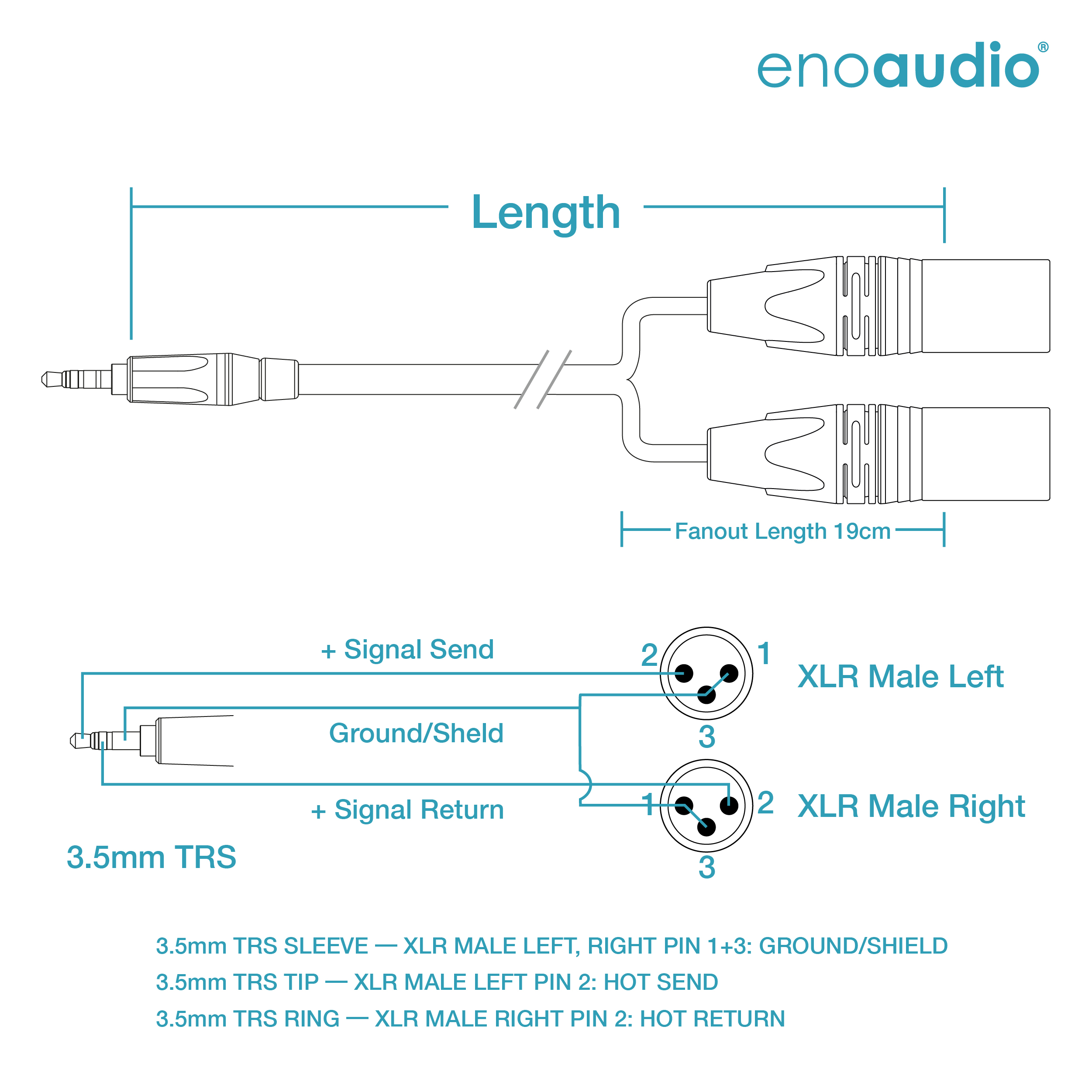
Mogami 2534 Quad Y Cable Amphenol 3 5mm Mini Trs Neutrik Xlr Male L R Hifi Enoaudio from enoaudio.de How to solder the connections for a standard 3pin xlr female. Mx 3 pin 4 pin & 5 pin mini xlr type connector is a type of connector used for many professional audio applications. Xlr pin 2 = low impedance audio hot (amphenol pin 4, white wire, typically) xlr pin 3 = low impedance audio return (amphenol pin 3, black wire, typically) note: Pin 1 = s+b pin 2 = r. 4.8 out of 5 stars 7. It contains instructions and diagrams for various kinds of wiring methods and other items like lights, windows, and so forth. The mini xlr has become quite popular in the headphone market as it is relatively small, it locks in place, and the connections are more reliable than your average trs. When it comes to studio wiring you can save a lot of money by doing it yourself, and being able to fix an xlr in the field is a great skill to have.
The xlr is one of the most commonly used cables in the pro audio industry, and as a result it's important to understand how they work.
Balanced audio uses a cable made up of two conductors that are twisted. The plastic pieces holding the headband in place have small indents where the wire enters and exits (red circle below). Xlr to 14 trs connector wired for balanced mono the usual way to connect a 3 pin xlr to a 14 trs aka stereo jack plug is to use the following pin allocation. For a mono output onto an xlr connector, you must use the following cables: Pin 1 = s 10k pin 2 to w 1uf pin 2 to w connectshield to xlr shell diagram: Replacement male xlr connector with three pins for your battery charger. Xlr pinout (balanced) a balanced system is used in pro audio systems (xlr wiring diagram shown below), with an overall screen covering a twisted pair. Amphenol 1/4″ trs, 3.5mm trs, neutrik 4 pin xlr, 4.4mm trrrs (pentacon), or 2.5mm trrs. In addition, it may be helpful to label the wires prior to disassembly. The mini xlr has become quite popular in the headphone market as it is relatively small, it locks in place, and the connections are more reliable than your average trs. The following xlr 4 pin wiring diagram photo have been authored. Pin 1 = s+b pin 2 = r connectshield to xlr shell diagram: 4.8 out of 5 stars 7.
Mini xlr wiring / monoprice m1570 balanced cable guide xlr cable zadiustech. A wiring diagram usually gives assistance nearly the relative perspective and treaty of devices and. (the rear view is the end you solder from) here are the connections on each pin: Pin 1 = s+b pin 2 = r use w4 type headset connectshield to xlr shell diagram: Xlr connector wiring diagram together with 3 pin mini 5 pin xlr wiring diagram for center u2022 4 dmx diagrams rh gregorywein co 3 female end cable wiring xlr cable wiring diagram.
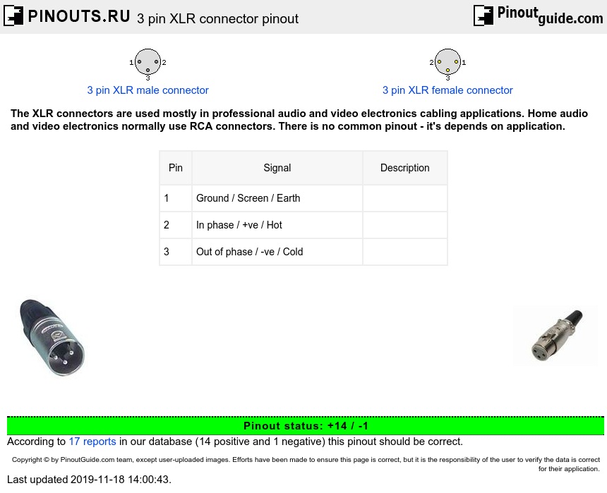
3 Pin Xlr Connector Pinout Diagram Pinouts Ru from pinouts.ru A wiring diagram usually gives assistance nearly the relative perspective and treaty of devices and. Pin 1 = s+b pin 2 = r connectshield to xlr shell diagram: How to solder the connections for a standard 3pin xlr female. Bridging 1&4 for signal, 2&3 for ground) 2. Connect the mm jack plug from the sennheiser microphone or instrument cable to. Pin 2 on the xlr is 'hot' and carries the positive going signal, whilst pin 3 is 'cold' and provides the return. 5 pin & 3 pin xlr wiring pinout information. A smaller version, the mini xlr connector, is sometimes used on smaller equipment.
Pro audio copper quality from canare cable.
Pin 2 on the xlr is 'hot' and carries the positive going signal, whilst pin 3 is 'cold' and provides the return. This can be done by either soldering the shield and negative wires of the xlr to the sleeve of the plug. Bridging 1&4 for signal, 2&3 for ground) 2. Balanced audio uses a cable made up of two conductors that are twisted. Xlr to 14 trs connector wired for balanced mono the usual way to connect a 3 pin xlr to a 14 trs aka stereo jack plug is to use the following pin allocation. The above diagram shows you the pin numbering for both male and female xlr connectors, from the front and the rear view. Pin 1 = s+b pin 2 = r connectshield to xlr shell diagram: In addition, it may be helpful to label the wires prior to disassembly. Pro audio copper quality from canare cable. It shows the components of the circuit as simplified shapes, and the capacity and signal links together with the devices. Collection of xlr to mono jack wiring diagram. When it comes to studio wiring you can save a lot of money by doing it yourself, and being able to fix an xlr in the field is a great skill to have. Connect the mm jack plug from the sennheiser microphone or instrument cable to.
